Electrical Conductivity: The Basics
There are two fundamentally different types of electrical conductivity:
- In Metals: electric current is carried by electrons.
- In Liquids: electric current is carried by ions.
Every electrochemical process — galvanic cells, electrolysis, electro-analysis — involves both types. The junctions where they meet and transfer electrical charge are Metal-Liquid Interfaces, historically called electrodes.
In a copper-silver galvanic cell, for example, one electrode undergoes oxidation:
While the other undergoes reduction:
This is how current carried by electrons in a wire becomes current carried by ions in solution.
The ISE Electrochemical Circuit
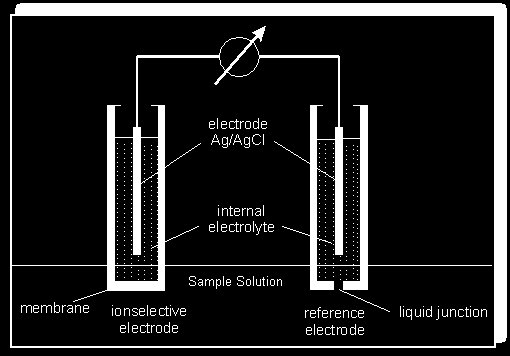
An ISE (with its own internal reference) is immersed in an aqueous solution alongside a separate, external reference electrode. The complete electrochemical circuit is formed when these are connected to a sensitive millivolt meter via low-noise cables.
A potential difference develops across the ISE membrane as target ions diffuse through from the high-concentration side to the lower-concentration side. This potential is what we measure.
The Nernst Equation
At equilibrium, the membrane potential is described by the Nernst equation. In simplified form, the measured voltage is proportional to the logarithm of the activity (effective concentration) of the target ion:
Where: R = gas constant, T = temperature (K), n = ionic charge, F = Faraday constant, A = ion activity
The electrode slope — millivolts per decade of activity/concentration — is a key indicator of electrode health:
| Ion Type | Acceptable Slope |
|---|---|
| Monovalent cations | +55 ± 5 mV/decade |
| Monovalent anions | −55 ± 5 mV/decade |
| Divalent cations | +26 ± 3 mV/decade |
| Divalent anions | −26 ± 3 mV/decade |
The slope decreases as the electrode ages or becomes contaminated — a lower slope means higher measurement errors.
The Reference Electrode
The membrane potential cannot be measured directly — it must be measured relative to a stable reference. The most common system is silver wire coated with solid silver chloride immersed in saturated KCl/AgCl filling solution:
This half-cell provides a constant potential of +205 mV relative to the Standard Hydrogen Electrode at 25°C, regardless of what ions are in the test solution.
Elyxir supplies two reference electrode types:
| Model | Type | Best Used With |
|---|---|---|
| ELIT 001 | Single junction AgCl/KCl | Ba, Ca, F, NO₂, Na, ClO₄ |
| ELIT 003N | Double junction lithium acetate | All ions (minimal interference) |
Calcium ISE: Membrane Mechanism
The calcium ISE has a PVC membrane impregnated with an organic molecule that selectively binds and transports Ca²⁺ ions. The internal solution contains a fixed concentration of calcium chloride.
- On immersion, Ca²⁺ ions begin diffusing across the membrane from high to low concentration.
- Positive charge builds up on the inside; negative charge increases outside.
- The resulting electric field opposes further diffusion.
- Equilibrium is reached when diffusion pressure equals the electrostatic repulsion — this is the membrane potential.
All other junction potentials in the circuit (liquid junction, metal-liquid interfaces) are assumed constant during calibration and cancel out.
Fluoride ISE: Crystal Membrane
The fluoride ISE uses a fundamentally different mechanism: a single crystal of Lanthanum Fluoride (LaF₃) doped with Europium Fluoride (EuF₂). The doping creates holes in the crystal lattice through which F⁻ ions can pass selectively.
- F⁻ ions pass through the crystal by normal diffusion — high to low concentration.
- Equilibrium develops between diffusion force and electrostatic repulsion.
- The only significant interference is OH⁻, which reacts with lanthanum to release extra F⁻. Eliminated by maintaining pH 4–8 with a buffer.
- The LaF₃ crystal is chemically robust and extremely selective.
Unlike the calcium ISE (where ions are transported by an organic carrier molecule), the fluoride ISE works by physical passage of ions through crystal defects. The result is exceptionally high selectivity — one of the most ion-specific ISEs available.
Further Reading
References:
- Harris D.C. (2001) — Exploring Chemical Analysis, 2nd Ed. ISBN 0716735407
- Skoog, West, Haller & Crouch (2000) — Analytical Chemistry, 7th Ed. ISBN 0030202930
- Christian G.D. (1994) — Analytical Chemistry. ISBN 0471305820
A Beginners Guide to ISE Measurements — 30-page in-depth guide by Chris Rundle covering calibration, reference electrodes, methods of analysis, and accuracy.
elyxir.co.uk/resources